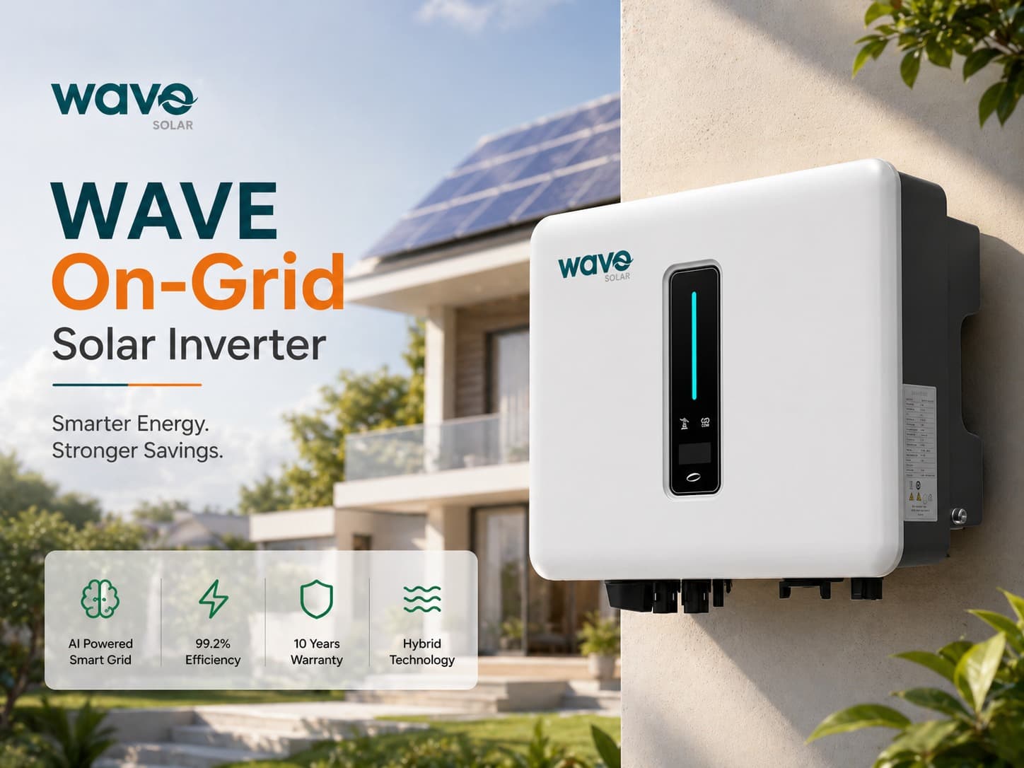
On-Grid Solar Inverter
Wave On-Grid Inverter: Setup & Troubleshooting Guide
2026-05-10T00:00:00.000Z•8
Wave on-grid inverters integrate well in commercial plants when you match the string design to the inverter’s MPPT limits, set the grid and communication parameters correctly, and verify every DC and AC connection before commissioning.
The safest approach is to design from the datasheet first, then wire, test, and only then energize the system.
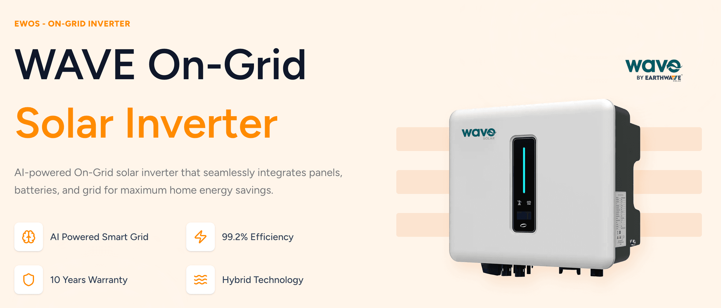
Use the Wave EWOS 5 to 25kW three-phase models for commercial plants. They support 2 to 3 MPPTs, 15A max input current per string, and up to 1100V DC max input voltage, with a 160 to 950V operating range.
Keep each string inside the inverter’s MPPT range and check Voc at cold temperature before you finalize module count.
Use separate MPPTs for different roof faces, tilt angles, or shading conditions. That keeps mismatch losses low.
Commission in steps. First verify insulation, polarity, open-circuit voltage, AC voltage, and grid parameters. Then enable the inverter and confirm stable grid sync.
For faults like no output, grid sync failure, or overvoltage trips, start with voltage, polarity, frequency, and insulation checks before replacing parts.
Three-phase Wave EWOS 5 to 25kW inverters fit most small to mid-size commercial rooftops and distributed plants.
For most commercial plants, these models work well when you want:
Lower balance-of-system complexity.
Stable grid injection with three-phase output.
Flexible string layouts across different roof zones.
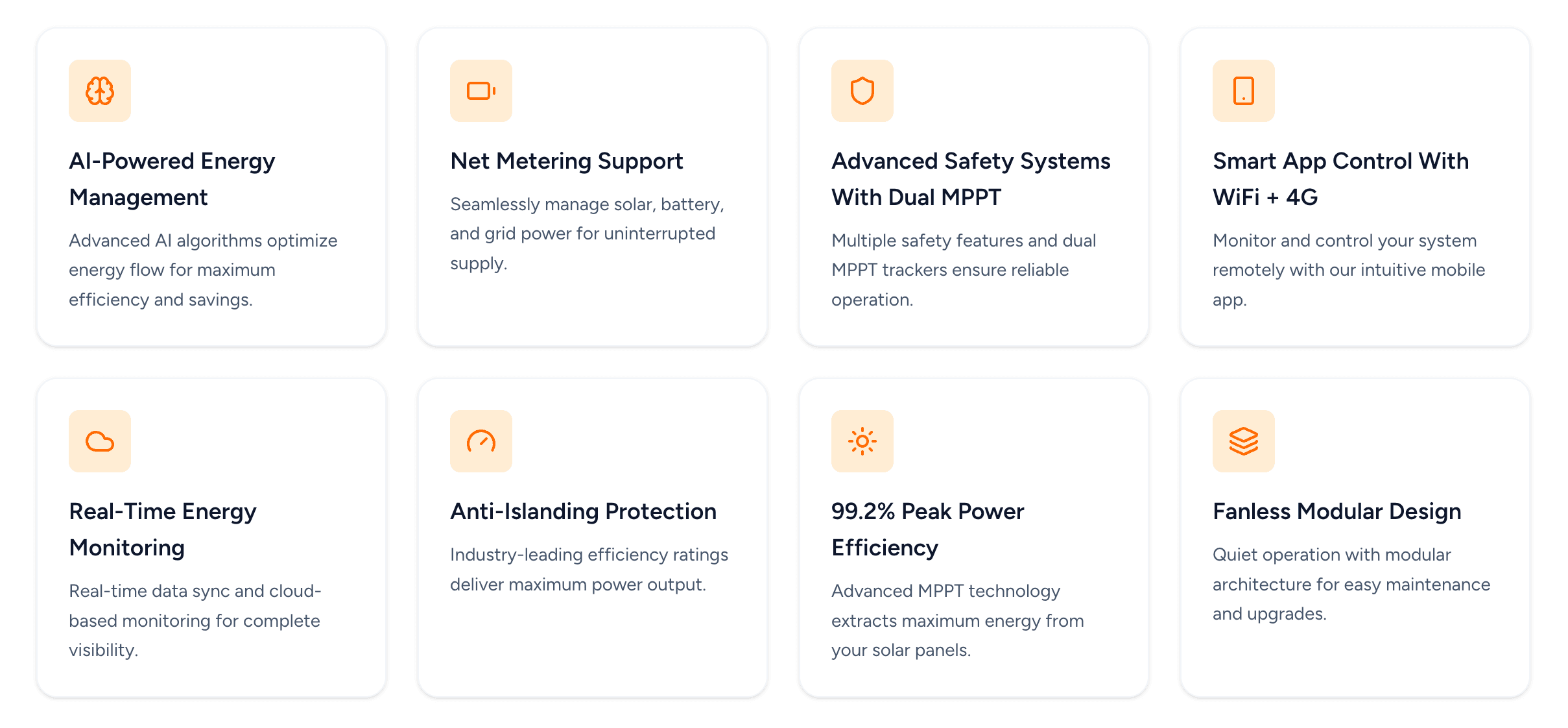
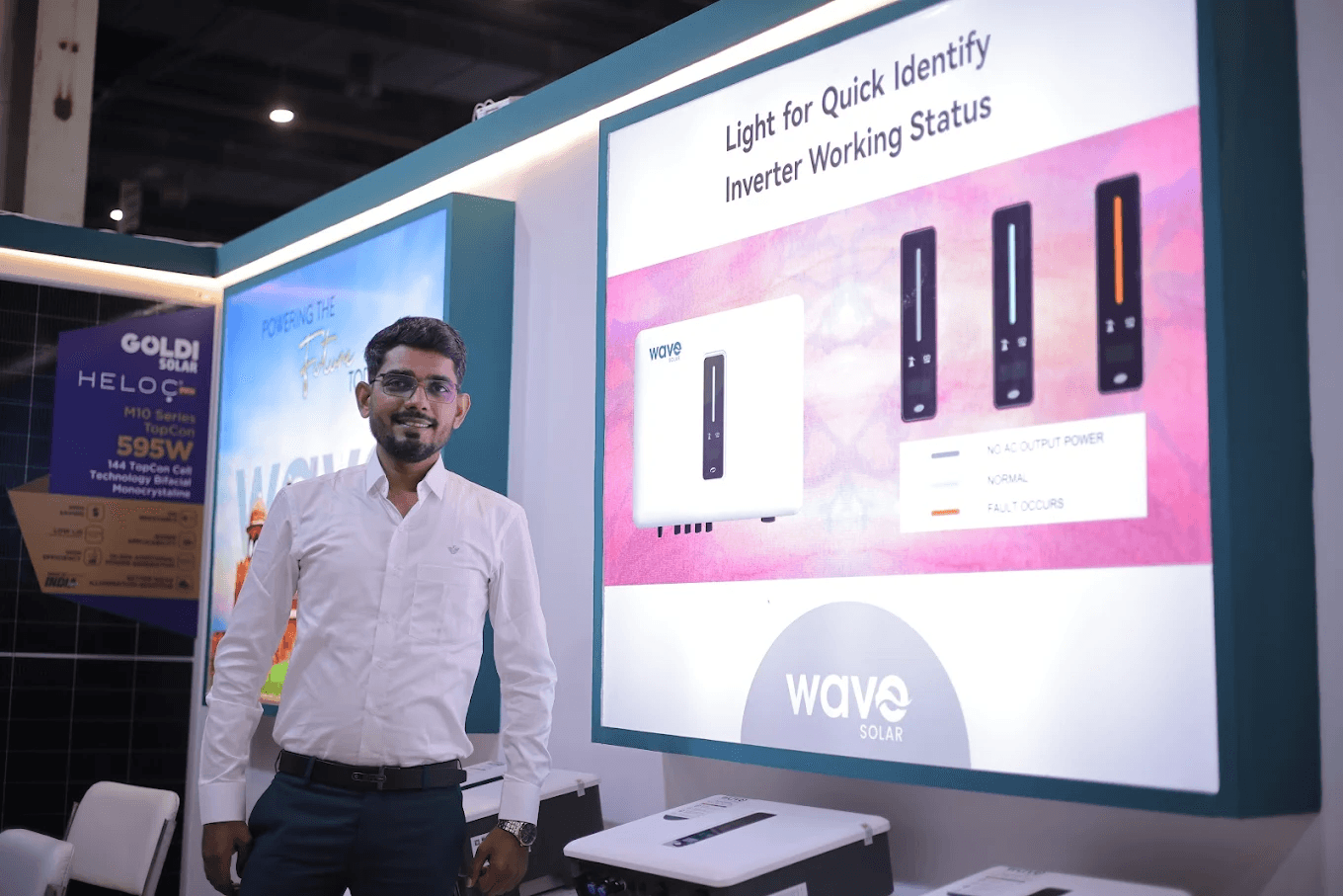
Simple O&M through OLED display, LED indication, and optional WiFi, LAN, or 4G monitoring.
For buyers comparing plant types, see Commercial Solar Solutions and Solar for Factories.
Earthwave also supports rooftop, commercial, and ground-mount solar projects with EPC, design, documentation, installation, and handover services.
The datasheet decides everything. If you ignore it, you risk overvoltage trips, MPPT mismatch, or poor energy yield.
Key EWOS 5 to 25kW limits you should use:
Start-up voltage: 180V.
Max DC input voltage: 1100V.
Rated DC input voltage: 620V.
Operating voltage range: 160 to 950V.
Max input current: 15A per input.
Max short-circuit current: 20A or 30A depending on model and MPPT input configuration.
MPPT count: 2 on 5kW, 6kW, and 8kW models, then 2 or 3 on some 10kW and 12kW variants, and 3 on larger 15kW, 20kW, and 25kW models.
If you want a wider product comparison, link this section to Best Solar Inverter Brands in India and Wave Inverters vs Leading Brands.
Set the inverter so each MPPT sees one clean electrical condition. That means similar module orientation, similar shading, and similar string length on each MPPT.
Verify the model and MPPT count from the project drawings.
Confirm the module string voltage stays inside 160 to 950V operating range.
Check that the string current stays below 15A.
Match each roof zone to one MPPT.
Enter grid voltage, grid frequency, and country code as per site utility rules.
Enable communication for monitoring and fault logs.
For commercial rooftop planning, you can also link to Rooftop Solar and Solar for Textile Units in Surat.
String size should keep cold Voc below the inverter limit and hot Vmp high enough for stable MPPT operation. That is the core rule.
Step 1. Find the module Voc and Vmp from the module datasheet.
Step 2. Apply the cold temperature correction to Voc.
Step 3. Multiply module Voc by the number of modules in series.
Step 4. Keep corrected string Voc below 1100V.
Step 5. Keep string Vmp within 160 to 950V during normal operation.
Step 6. Make sure string current stays below 15A.
Assume a commercial module with these typical values:
Voc = 49.5V.
Vmp = 41.5V.
Current = 13A.
Now test a 18-module string:
String Voc at STC = 49.5 x 18 = 891V.
If cold weather raises Voc by about 10%, corrected Voc becomes about 980V.
That stays below the 1100V max DC input limit.
Now check operating voltage:
String Vmp = 41.5 x 18 = 747V.
That sits inside the 160 to 950V operating range.
Current check:
String current = 13A.
That stays below the 15A max input current.
If your project is ROI-driven, connect this section to Commercial Solar Cost Savings and How Solar Reduces Peak Demand.
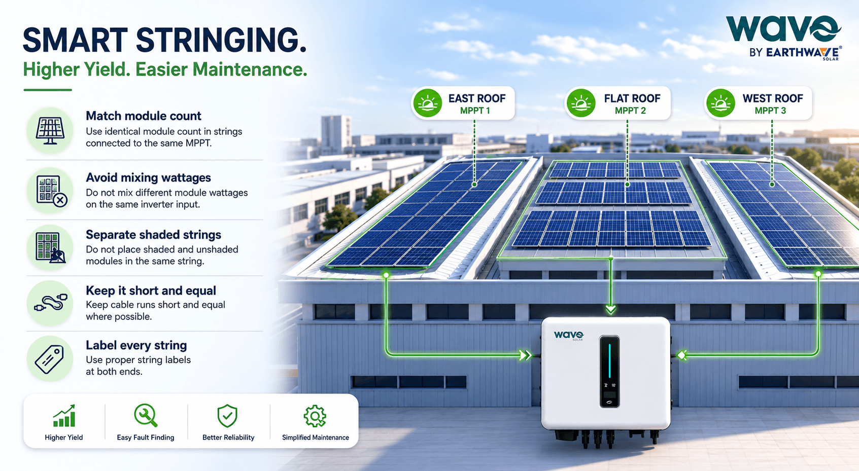
Good stringing reduces mismatch, improves yield, and simplifies fault finding. The best rule is simple. Keep one roof condition on one MPPT.
Follow these rules:
Use identical module count in strings connected to the same MPPT.
Avoid mixing different module wattages on the same inverter input.
Do not place shaded and unshaded modules in the same string if you can avoid it.
Keep cable runs short and equal where possible.
Use proper string labels at both ends.
East and west roofs on separate MPPTs.
Different tilt angles on separate MPPTs.
High-shade zones on separate inverters or separate trackers.
Long string pairs for large flat roofs, if voltage stays within range.
For more sector-specific planning, link to Solar for Hospitals in India and Solar IT Parks ESG Scope 2.
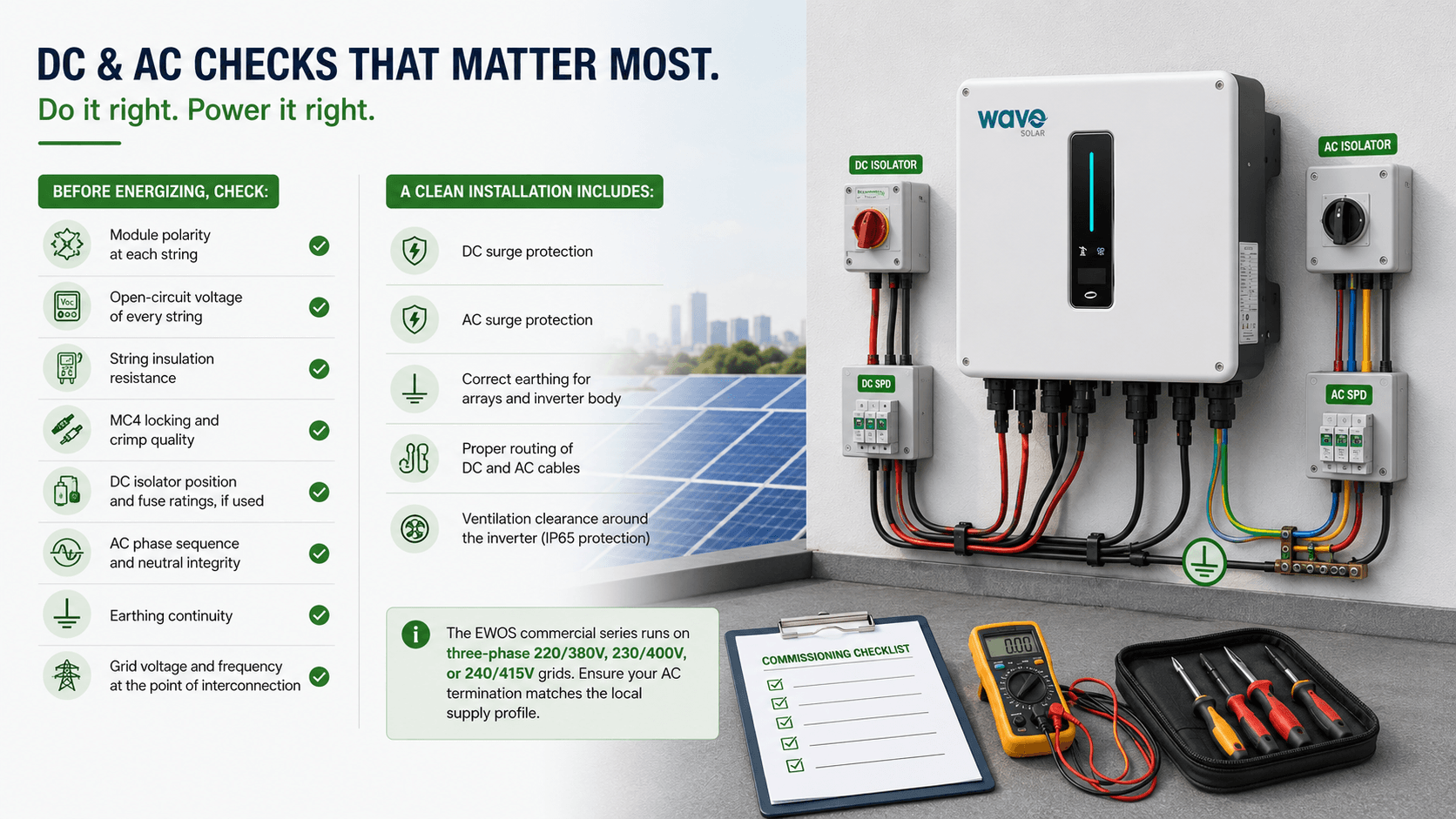
DC and AC checks prevent most first-day failures. If you do them in order, you save time and avoid rework.
Module polarity at each string.
Open-circuit voltage of every string.
String insulation resistance.
MC4 locking and crimp quality.
DC isolator position and fuse ratings, if used.
AC phase sequence and neutral integrity.
Earthing continuity.
Grid voltage and frequency at the point of interconnection.
For the AC side, make sure cable size matches inverter output current and site voltage drop targets. The EWOS commercial series runs on three-phase 220/380V, 230/400V, or 240/415V grids, so your AC termination must match the local supply profile.
DC surge protection.
AC surge protection.
Correct earthing for arrays and inverter body.
Proper routing of DC and AC cables.
Ventilation clearance around the inverter, even though the unit has IP65 protection.
If you want a checklist-driven operational guide, link this part to Solar EPC Company Checklist India.
Commissioning should follow a fixed sequence every time. That makes the process fast and repeatable.
Confirm mechanical mounting is tight and level.
Verify all DC strings with a meter.
Verify DC polarity.
Confirm insulation resistance.
Check AC cable termination and torque.
Confirm grid voltage and frequency.
Power the inverter and watch the display.
Confirm start-up above 180V.
Check MPPT voltage and current on the display or app.
Confirm export begins only after stable grid sync.
A good commissioning result looks like this:
No insulation alarm.
No reverse polarity alarm.
Stable grid connection.
Output power rises smoothly with irradiance.
Communication data appears in the monitoring platform.
For project handover workflows, you can link to Commercial Solar Solutions and Earthwave Contact Page.
Most Wave inverter faults come from wiring, string voltage, grid conditions, or communication issues. You can solve many of them on site without changing hardware.
Check these first:
String voltage is above 180V start-up voltage.
String polarity is correct.
DC switch is on.
Insulation resistance is healthy.
The inverter is not in standby because of low irradiance.
Real-world example. A commercial rooftop in early morning may show no output until irradiance rises. If the string voltage is below start-up level, the inverter waits. That is normal behavior, not a defect.
Check these first:
Shade on one or more strings.
Mixed roof orientations on one MPPT.
Loose DC connector.
Dirt on modules.
String current capped by a poor module match.
Wrong monitoring settings or curtailed export setting.
Check these first:
Grid voltage is outside the allowed window.
Grid frequency is unstable.
Phase sequence is wrong.
Neutral or earthing is weak.
Utility settings do not match the local grid code.
Check these first:
String Voc is too high in cold weather.
Number of modules per string exceeds safe limit.
Site temperature is much lower than design assumed.
You used the wrong module model in design.
If the issue repeats across sites, compare it with Wave Inverters vs Leading Brands so your procurement team can benchmark reliability and specs.
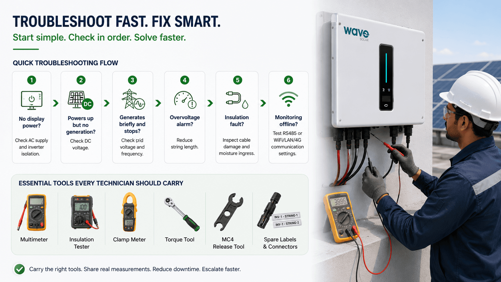
Start with the easiest checks first. That saves time and avoids unnecessary part replacement.
If there is no display power, check AC supply and inverter isolation.
If the inverter powers up but does not generate, check DC voltage.
If it generates briefly and stops, check grid voltage and frequency.
If it shows overvoltage, reduce string length.
If it shows insulation fault, inspect cable damage and moisture ingress.
If monitoring is offline, test RS485 or WiFi/LAN/4G communication settings.
Multimeter.
Insulation tester.
Clamp meter.
Torque tool.
MC4 release tool.
Spare labels and connectors.
This reduces downtime. It also makes escalation faster because you can share actual measurements, not guesses.
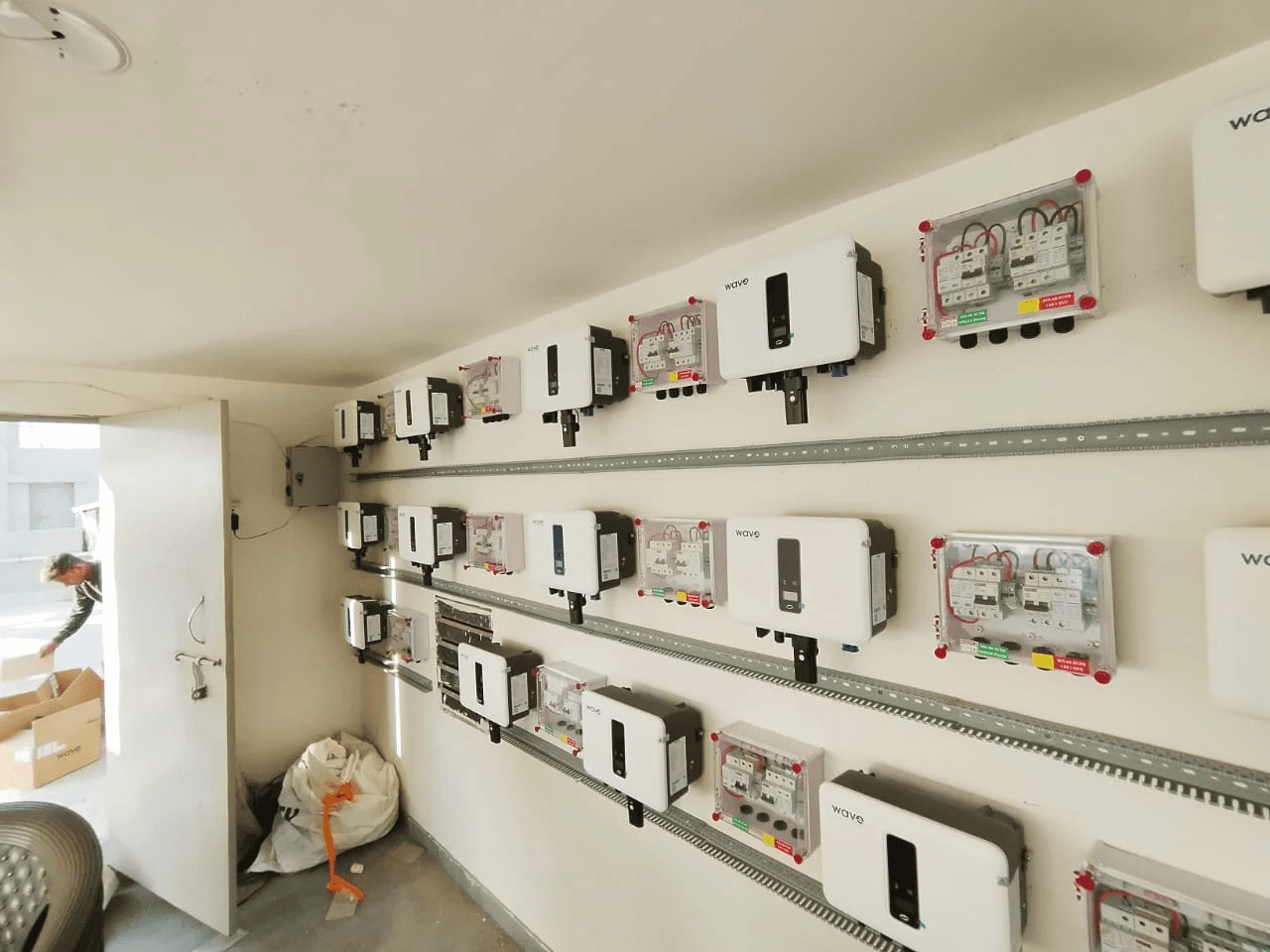
Earthwave Solar supports commercial and rooftop solar work through EPC, site survey, design, documentation, installation, and handover.
The company also highlights commercial and industrial systems, ground-mount projects, and Wave inverter solutions with monitoring and warranty-backed deployment.
Their brochure shows services for rooftop, commercial, and ground-mount systems, plus project execution across Gujarat and Madhya Pradesh.
It also lists a structured process from consultation to final handover, which suits commercial buyers who want one team for design, installation, and paperwork.
For project teams, this matters because inverter integration is not only an electrical task. It also needs design support, bill-of-material validation, and after-sales O&M planning. Earthwave positions itself around that full delivery model.
A final checklist prevents avoidable callbacks. It also gives your EPC or O&M team a clean handover record.
Use this checklist before sign-off:
Correct inverter model installed.
Correct MPPT allocation.
All string voltages measured and recorded.
Polarity verified on every string.
AC voltage and frequency verified.
Earthing complete.
Surge protection installed.
Monitoring platform online.
All alarms cleared.
Commissioning log signed.
For commercial plants, this one habit protects ROI. A well-checked inverter starts faster, trips less, and gives more stable generation data for CFO review and ESG reporting.
The exact count depends on module Voc, site minimum temperature, and the inverter model. A safe design keeps cold Voc below 1100V and operating voltage within 160 to 950V.
You should avoid that. Different orientations create mismatch, reduce yield, and make fault diagnosis harder. Use separate MPPTs for different roof faces whenever possible.
The string voltage may be below the 180V start-up threshold, or the DC voltage may be outside the allowed operating window. Check string wiring, irradiance, and module count first.
Check grid voltage, frequency, phase sequence, and earthing. If any of these sit outside limits, the inverter will not sync safely.
The EWOS commercial series offers three-phase output, up to 98.6% max efficiency, IP65 protection, 2 to 3 MPPTs, and practical monitoring options. That combination suits rooftop and distributed commercial plants well.
Use the Wave datasheet at design stage, then book a site survey and commissioning review before you energize the plant.
For commercial rooftops, Earthwave Solar can support EPC, inverter selection, stringing validation, and handover for your project.
Contact Earthwave Solar here: Contact Earthwave Solar.
FAQS
Can't find the answer you're looking for? Our team is here to help.
SUBSCRIBE NEWSLETTER
Switching to solar is easier than you think. Let us guide you to cleaner, more affordable energy.
